NPN Transistor: A Fundamental Semiconductor
1. Definition
Negative Positive Negative semiconductor also known as NPN transistor for the intimate, is a three-terminal semiconductor device used to amplify* or switch* electronic signals. It consists of three regions: the emitter, base, and collector. The terminals are typically labeled as follows:
- 1: Emitter
- 2: Base
- 3: Collector
The structure can be visualized as a three-pin device with the following pinout:
       (2)
        |               -------------
        |               |     |     |
    ---------   or      |     |     |
    |       |           |     |     |
    |       |          (1)   (2)   (3)
   (1)     (3)
2. Function and Operation
Key Roles of Each Terminal:
- Emitter (1): Emits electrons into the circuit.
- Base (2): Controls the flow of electrons between the emitter and collector.
- Collector (3): Collects electrons for the emitter.
How It Works:
- The collector draws electrons from the upper voltage side of the circuit.
- The emitter releases electrons to the lower voltage side.
- The base acts as a gate: it must receive a minimum current to allow
electron flow. Without this current, the transistor blocks the path (acts as a
switch).
TIP
The base current acts as a trigger to control the flow of current between the
emitter and collector.
3. Practical Application: Circuit Breaker Example
Simple Switching Circuit
The NPN transistor can function as a switch in a circuit. Here’s how it works:
-
Without Base Current:
- The transistor remains off, blocking current flow (like a closed circuit
breaker).
- The transistor remains off, blocking current flow (like a closed circuit
-
With Base Current:
- When a given switch connects the base to a voltage source, the transistor
turns on, allowing current to flow through the collector-emitter path and
lighting an LED.
- When a given switch connects the base to a voltage source, the transistor
DANGER
High voltage can damage/fry the transistor. Always use appropriate voltage levels
and protective components (e.g., resistors, voltage regulators) to avoid overloading
the device.
4. Visual Representation
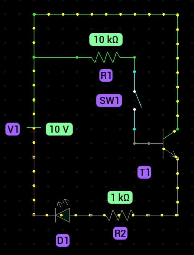
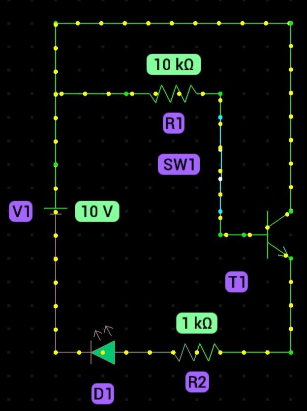
Observation:
- In the first image, the NPN transistor blocks current despite an incoming
signal. - In the second image, closing the base switch activates the transistor,
completing the circuit and turning on the LED.